Why Inverse Lithography (ILT)?
Problem: Smaller chips require more resolution enhancement techniques (RETs). Traditional approaches are expensive, prone to failure, and not perfect.
Solution: Curvilinear masks use curves rather than orthogonal polygons, computed by ILT to maximize the process window — the margin for error in lithography. Benefits include:
- Bigger process window and more robust wafer shapes at advanced nodes (optical + EUV), improving yield margins
- Improved depth of focus → less sensitivity to focus drifts; better contact fidelity
- High-NA EUV (0.33 → 0.55) is expected to make curvilinear masks a necessity
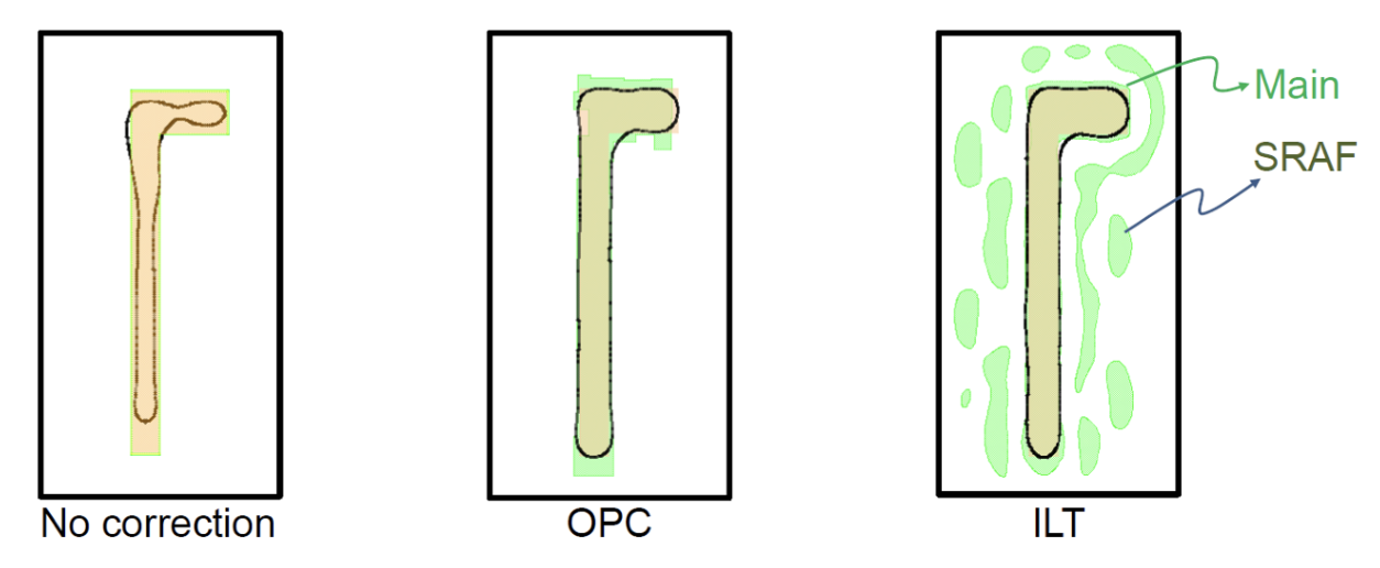 Figure 1: Optical proximity correction (OPC) vs. inverse lithography (ILT) mask design.
How Does ILT Work?
ILT treats mask design as an inverse math problem. It creates optimized, curvilinear mask shapes that include main patterns and sub-resolution assist features (SRAFs).
- Forward Simulation — Simulates light diffraction, predicting the wafer image from an initial mask design.
- The Cost Function — Compares the simulated image against the desired pattern to calculate error.
- Gradient Descent — Minimizes the error; indicates which way to adjust the mask’s curves and pixels.
- Iterate — The system continuously loops this process until the error approaches zero.
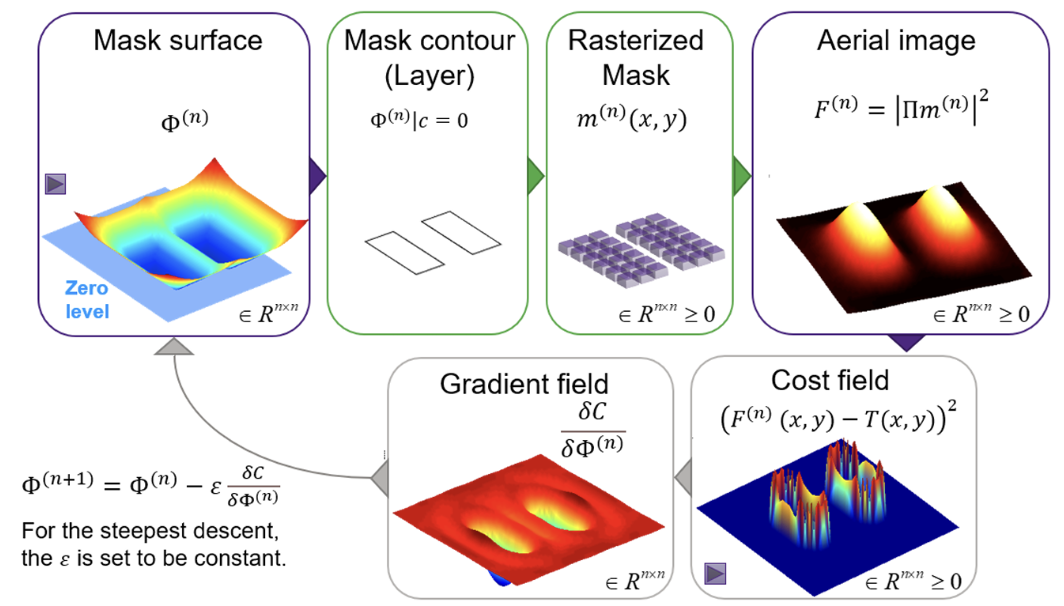 Figure 2: Iterative ILT optimization loop.
Current Challenge + Proposed Model
| Challenge | Description |
|---|---|
| Slow physics simulations | Current ILT relies on expensive forward lithography models and gradient descent |
| Non-convex optimization | The problem is highly non-convex; algorithms get stuck in sub-optimal local minima |
| High compute cost | Thousands of CPU/GPU hours per chip layer |
Proposition: Move ILT from a pure physics simulation to a conditional sampling task, analogous to the relationship between the finite element method (FEM) and physics-informed neural networks (PINNs) — learn the solution manifold from data rather than re-solving the PDE from scratch every time.
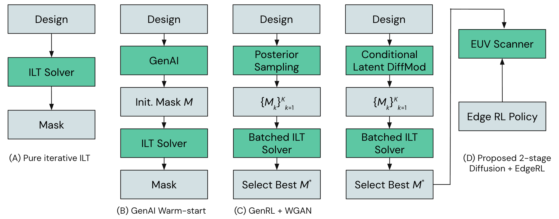 Figure 3: Proposed generative ILT architecture overview.
Diffusion Models for Mask Generation
Replace posterior sampling with a Conditional Latent Diffusion Model (LDM):
- Input the ideal circuit layout as the condition
- The model denoises a latent canvas into a photomask
- For variable-shaped beam (VSB) writers instead of multi-beam mask writers (MBMW), a diffusion transformer can natively generate discrete, constrained geometries — e.g., tokenizing Manhattan constraints to force 90° shapes
Advantages:
- Inherently learns the manifold/shape of optimal masks from historical data
- LDM learns a global shape manifold → no need to chase local gradients at every iteration
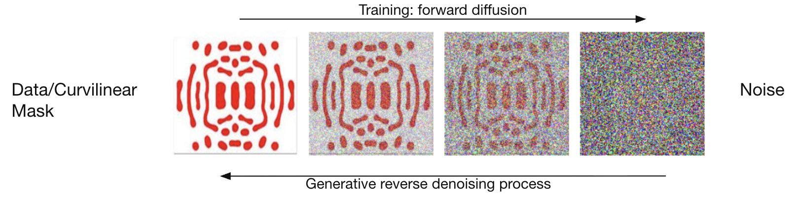 Figure 4: Conditional latent diffusion for photomask synthesis.
Generative Reverse Denoising Process
The diffusion model learns to reverse a forward noising process: starting from Gaussian noise and progressively denoising toward a valid mask conditioned on the target layout. This framing replaces iterative gradient descent on a physics simulator with a single forward pass (or few-step sampler) through a learned generative model.
1 Yang, H., & Ren, H. (2026). Pushing the Limits of Inverse Lithography with Generative Reinforcement Learning. arXiv preprint arXiv:2602.16089.
Generative Reinforcement Learning
Problem with pure diffusion: Statistically plausible masks can still fail strict EUV physics checks, causing Edge Placement Errors (EPE).
Solution: Fine-tune the diffusion model using Group Relative Policy Optimization (GRPO) — eliminating the need for a critic model from standard PPO by utilizing group-reward sampling.
Proposed Control Loop
- RL agent generates a batch of mask candidates
- Candidates are evaluated via a differentiable lithography simulator (e.g., TorchLitho 2.0)
- Reward function: Minimize simulated EPE and maximize the process window
- Result: The RL agent teaches the model to escape bad minima and generate physically valid masks
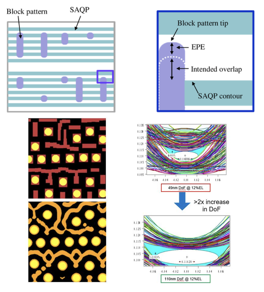 Figure 5: Process window vs. edge placement error trade-off under GRPO fine-tuning.
Two-Stage Control Method
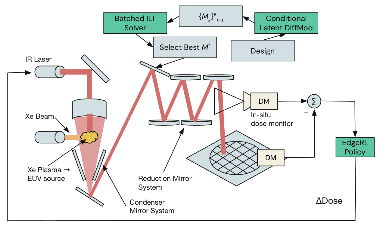 Figure 6: Dual-stage offline mask synthesis + online EUV dose control.
Edge-Level Control
- Compiled RL policy connects directly to the EUV scanner
- Model quantization: GRPO-trained policy is quantized for low latency
- Deployed onto the scanner’s FPGA
- Operates at the 50 kHz frequency of the EUV droplet generator ($\Delta\text{Dose}$)
- Real-time compensation: The edge agent dynamically modulates the EUV laser dose to counter stochastic defects during printing
Comparison to State of the Art
| Feature | Generative ILT | Dual-Stage Control (Proposed) |
|---|---|---|
| Domain | Offline RL | Offline RL + GRPO Edge RL |
| Failure Handling | Passive / statistical: designs a mask mathematically less likely to fail | Active / deterministic: modulates laser to suppress random photon noise |
| Tool Awareness | Blind to EUV scanner dynamics | Real-time adaptation |
| Architecture | Single-stage (Diffusion → Mask) | Dual-stage (Latent Diffusion → Mask and RL Agent → Laser) |
Proposed Software Advantages
- GANs are prone to mode collapse → LDM explores the full solution space
- AdaIN injection misses local geometry → LDM cross-attention places SRAFs where needed
- WGAN requires carefully balanced networks → LDM denoising is stable and scales easily
Summary
This project proposes a generative framework for inverse lithography that combines conditional latent diffusion for fast curvilinear mask synthesis with GRPO-based reinforcement learning to enforce EUV physics constraints. A dual-stage architecture extends this offline optimization with real-time laser dose modulation at the scanner edge — bridging the gap between statistically correct masks and deterministically reliable wafer prints as nodes continue to shrink.